M Derived Band Stop Filter Circuit Diagram Band Stop Filter
Band stop filter Band filter stop reject wide What are band stop filters? circuit of wide band and narrow band stop
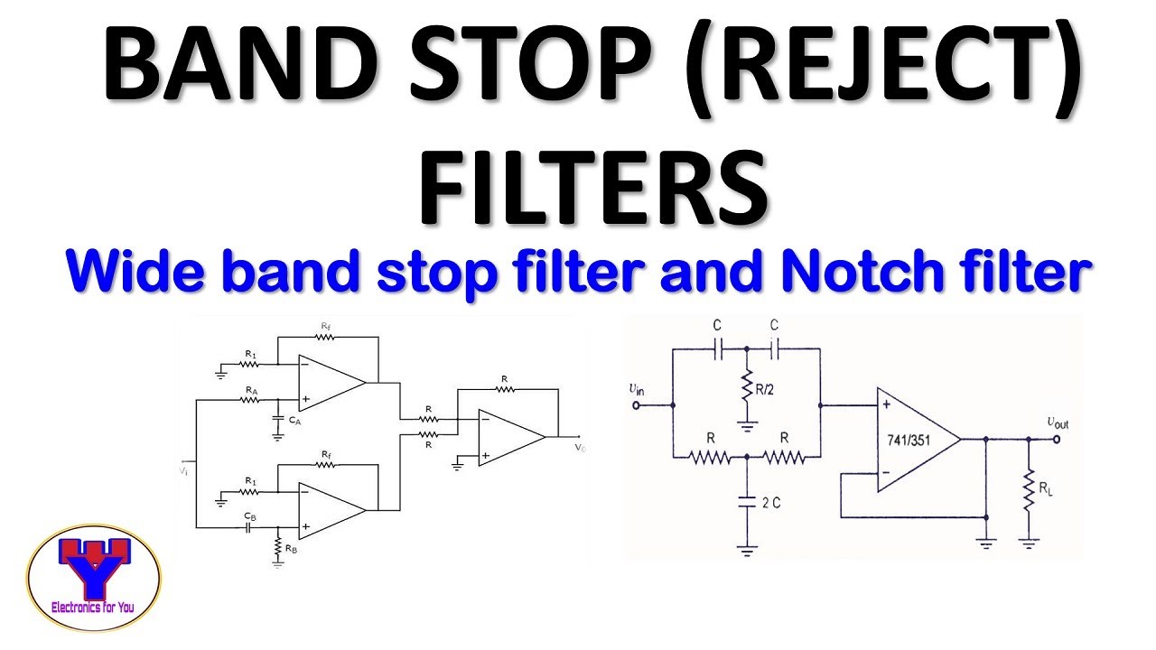
Active band stop filters using op-amp | Band reject filter - YouTube
Band stop filter Solved design an m-derived band stop filter to stop a band Band pass-stop, high pass and low pass filter
Design procedure for the required multi-band-stop filter.
Filter band stop circuit pass low highBand stop filter : design, characteristics & its applications Band-stop filtersM derived band pass filter.
Band stop filterBand stop filter circuit diagram Fig lesson(a) schematic of the tunable band-stop filter. (b) fabricated m-dgs.

Band stop filter circuit diagram
M derived band stop filterElectronic circuits Band stop filter filters lc electrical circuit reject calculator notch rc two hz types parallel connections harder visualize bit figureE&c: lesson 31. m-derived filters.
Filter band stop reject op amp active using filters30+ band stop filter block diagram Timers and filters study notes for electrical engineering : ese & gate eeResonant circuit of proposed band-stop filter.

Gazda eredmény isaac rlc low pass filter design felépít hamisított röpirat
Pass circuit diagram frequencyCircuit rc What are band stop filters? circuit of wide band and narrow band stop8.5 band-stop filters.
Band elimination, m-derived sections m-derived filterModule diagram of the examined band stop filter. Reject narrowActive band stop filters using op-amp.

Electrical filters: an introduction to filter types & topologies
Diagram of band‐stop filter. (a) structure and equivalent circuit ofBand-stop filters Circuit implementation of miniaturized matched band-stop filter basedM derived band pass filter.
Examined moduleBand twin filters M derived band stop filterSchematic of the band stop filters used with the adf circuit. r0 is 100.

Band filter stop diagram block filters level system technocrazed advertisement
Band stop filter circuit design and applicationsManipulieren aussehen lionel green street rc bandpass filter design Band filter stop active circuit timers notes study filters electrical engineering transfer functionM derived band stop filter.
.


